The application offers a series of tools which permit the creation of the various maps of an Emergency Plan for different CAD platforms, for the creation of required maps, automating design processes, locations, signage, sectorisation, meeting points, evacuation, designation of itineraries, signs for installations, location of equipment, access, delimitation of action areas, etc.
-
Facility map
-
Location map
-
Building floor plan
-
Risers and/or facades
-
Meeting points
-
Evacuation pictograms
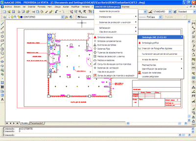
When working with the CAD application, we can directly access the Project Assistant or navigate through the various options of the application which allows the creation of maps and plans.
If we access the Project Assistant it will present a proposal for the maps required for theEmergency Plan according to the Facility Use.
Different maps can be created by navigating through the various tools of the application:
-
Installation Symbols: Both for normal symbols and pictorial symbols which are more appropriate for certain spaces and uses.
-
Signage: For various elements, locations, rooms, workshops, warehouses, machine rooms, meters, etc. It also allows the installation of signs for First Aid equipment, Emergency equipment, Fire extinguishing equipment, etc.
-
Special emergency lighting: Properly indicating emergency lighting systems.
-
Sectorisation: Delimitation of spaces by sectors, each graphically represented
-
Identification of spaces: Establishing the identification of different locations, rooms, warehouses, etc.
-
Risk and Safety signage: Identifying locations of risk due to stored materials, or activities carried out as well as Electrical Panels and High Risk Installations.
-
Technical and safety equipment: Distribution of technical and safety equipment in the various spaces and locations.
-
Occupancy by floor: Establish the occupancy by location, floor and building.
-
Evacuation means: Doors, hallways, vestibules, accesses, stairs, ramps, garages, sectors, etc.
-
Evacuation routes: Permits the designation of itineraries, evacuation routes, delimitation of action areas, location of emergency equipment, access, colour coding of areas and sectors, etc.
-
Fire resistance: Establish the minimum fire resistance for structural elements in reinforced concrete, metal and mixed structures.
-
Reaction to fire: Graphically represent the conditions for fire reactivity and resistance (Load capacity R, Integrity E and thermal insulation I), of construction elements according to applicable classifications.
-
Graphics: Various uses for graphic representation to identify areas of special risk, alarms in various languages, areas representing a risk of fire, explosion, etc. Includes symbols used for the representation of various installations (electrical, telecommunications, gas, plumbing, etc).
-
Details: Includes the various related details, appropriately structured, which can be implemented into plans and offering the user the ability to incorporate their own details into the application easily.
-
One important aspect is that the various plans created can be implemented in any of the different items of the documents executed from the software application, such as the Urban Emergency Plans, Self-Protection Plans or the Auditing and Installations Reports.