pissuCAD

Commercial

Version:2015

Languages:English;Turkish

Size: 500 MB

Update Date:2015-02-13

Industry:Civil

Required application:


  • Detailed Introduction
  • Key Features
  • Screen shot
  • Publisher

DRAWING THE NETWORK

AnkiSOFT Yazılım's wastewater (sewerage) network hydraulic design software, pissuCAD; is developped for wastewater network of infrastructure projects. It is for to draw/modelling/design/analyse the wastewater network under AutoCAD or ZWCAD.

It is possible to arrange the drawing style by using STYLE MANAGER, so you can use different drawing style in different projects.

OPEN LAYER command can open all the necessary layers that the software needs.

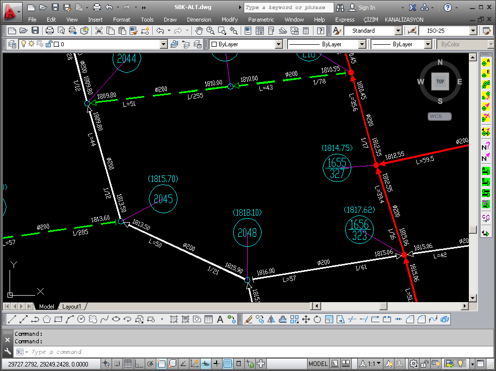
You can define/draw/edit/delete/move manholes, can change some/all properties of manholes. The software will write; manhole-number and the elevation for each manhole on the drawing.

You can find any manhole by searching the manhole-number, can change the location of manhole-number, can renumber some/all manholes from a specified number.

You can define/draw/edit/delete pipes, can change the direction of pipes, can change some/all properties of pipes. The software will write; start-invert-elevation, diameter, length, slope and end-invert-elevation for each pipe on the drawing.

You can show depths, discharge and fullness ratio of all pipes on the drawing.

You can define/draw/delete pump-station/fosseptic.

You can define/draw/delete point-discharge to any pipes.


CHECKING

You can check weather there is any mistake in the network model. You can find and you can correct them.

Such as; same manhole-numbers, 1st phase - 2nd phase - existing pipe connections, pipe connections from/to manholes, pipes going from lower elevations to higher elevation.


HYDRAULIC CALCULATIONS

During design works; the Network-Drawing-Software will work together with the Hydraulic-Calculation-Software.

To do this; all the informations on the drawing will be send to calculation, the calculation software will do hydraulic calculations, then all the calculated informations will be send back to the drawing to show the final situation.

You can repeat this process, untill you reached to the situation that you want.


DESIGN CRITERION

You can define;
• Allovable minimum elevation difference for pipes
• Allowable minimum water drop head depth
• Pipes can have circular cross-section or rectangular cross-section (box).
• For each pipe; a type-name, material (concrete, reinforced concrete, PVC, ACB, Steel, HDPE, Ribloc, ...), inner diameter, allowable minimum slope, allowable maximum slope, allowable maximum fullness ratio, design formula (Kutter, Manning, ...), "a" or "n" values (roughness ratio) for the formula.


DESIGN CALCULATION TABLES

Hydraulic calculations are in the form of tables and recorded in a text file.
• Start manhole-number
• End manhole-number
• Phase number
• Discharge area number
• Pipe length
• Unit discharge
• Manhole-number bringing water
• Amounth of coming water
• Q total
• Start ground elevation
• End ground elevation
• Inner-top elevation of pipe at the start
• Inner-top elevation of pipe at the end
• Inner-bottom elevation of pipe at the start
• Inner-bottom elevation of pipe at the end
• Inner-top depth of pipe at the start
• Inner-top depth of pipe at the end
• Slope
• Selected diameter
• Fullness ratio
• Capacity at %50 fullness
• Velocity
• Water depth
 

Next table contains; pipe lengths according to pipe diameter and phase of pipe.

The last table contains; excavation amounts according to excavation depth and phase of pipe.


GENERAL LAYOUT PLAN (1/5000)

The software will show collector pipes and mannoles automatically. Also, you can decide for other pipes/manholes to show on general layout plan.

Then, you can prepare general layout plan in a very short time.


PROFILE DRAWING

Now, everything is ready after design works. So, it is easy for you to prepare the profile.

The only thing that you have to do is; to decide the phase (1st-phase/2nd-phase/existing).

After writing vertical and horizantal scale, you can prepare the profile by the use of only one command.

By the use of profile software;
• You can draw profile without any length limit at one time.
• The drawing-height is set to 297mm.
• To be able to draw the profile within the drawing-height, referance elevations will be arranged automatically.
• The informations on the profile are;
• Pipe depth
• Referance elevation
• Manhole-numbers for connected pipes
• Manhole-number
• Ground elevation
• Inner-bottom elevation of pipe
• Pipe length
• Slope (1/a)
• Pipe diameter/box sizes
• There will be an empty place on the right side of the drawing for legend.
• There will be a border line for the drawing, also another border line for cutting.
• The output is in DXF file-type.


DETAILED EXCAVATION

The purpose of this software is to prepare the excavation amounts in detail for wastewater network.

It is easy for you to get the amounts, because, all the informations are ready after the design works.

You can define some general informations; excavation slope, the road pavement thicknesses (asphalt, conrete, stone, stabilized, natural).

For typical manholes; type-name, inner diameter, outer diameter, width of concrate basement, bottom width of excavations (slopped excavation, wooden-bracing, steel-bracing and 5 different sheet-pile-wall), the backfill thicknesses (basement improvement layer, basement layer and basement concrete).

For typical pipes; pipe-class in the network (small-diameter, medium-diameter or collector), pipe-name, backfill-type-number, inner diameter, outer diameter, bottom width of excavations (slopped excavation, wooden-bracing, steel-bracing and 5 different sheet-pile-wall), the backfill thicknesses (basement improvement layer, basement layer and basement concrete).


EXCAVATION TABLES

The output table for manholes contains;
• Manhole-number
• Phase
• The greatest diameter of outgoing pipe.
• Inner diameter of manhole
• Outer diameter of manhole
• Width of basement concrete 
• Bottom width of excavation
• Inner-bottom depth of manhole
• Backfill thicknesses (basement improvement layer, basement layer and basement concrete)
• Excavation depth
• Excavation amounts depending on depths
• Total excavation amount
• Volume of the concrete manhole
• Road pavement informations (type, thickness, area and volume)
• Backfill amounts (basement improvement layer, basement layer and basement concrete)
• Backfill type and volume
• Excavation and type of bracing
• The depth of bracing
• The area of bracing
 
The output table for pipes contains;
• Start manhole-number
• End manhole-number
• Phase
• Pipe informations (diameter, outer diameter, bottom width of excavation and length)
• Bottom width of excavation for manhole
• Excavation length
• Inner-bottom depths at start and at end
• Backfill thicknesses (basement improvement layer, basemet layer and top backfill layer)
• Excavation depths at start and at end
• Excavation amounts depending on depths
• Total excavation amount
• Pipe volume
• Road pavement informations (type, thickness, area and volume)
• Backfill amount (basement improvement layer, basement layer and top backfill layer)
• Backfill type and volume
• Excavation and type of bracing
• The depth of bracing
• The area of bracing

During the excavation calculations;
if the excavation width at top is less than or equal to 1.00 m., the excavation is called as narrow-deep-excavation.
If it is greater than 1.00 m., then the excavation is called as wide-deep-excavation.


SUMMARY TABLES of DETAILED EXCAVATION

For manholes; excavation and bracing summaries are in the form of tables according to phase.

For manholes, at summary-total tables; excavation amounts according to depths, backfill amounts according to backfill-type, bracing amounts according support-type, road pavement amounts according to pavement-type, in the base of small-diameter, medium-diameter or collector.

For pipes; excavation and bracing summaries are in the form of tables according to phase.

For pipes, at summary-total tables; excavation amounts according to depths (for the both of narrow-deep-excavation and wide-deep-excavation), backfill amounts according to backfill-type, bracing amounts according bracing-type, road pavement amounts according to pavement-type, in the base of small-diameter, medium-diameter or collector.

For manholes+pipes; excavation, backfill and bracing summaries are in the form of tables according to phase.

For pipes;  pipe lengths at project and pipe lengths at construction are in the form of tables according to pipe diameter and phase.


INFORMATION TRANSFER

You can transfer easily all the network informations to another drawing/computer, or vice versa. 


GENERAL

• There is no limit to the number of manholes and pipes.
• There is no limit to the number of pipe diameters and pipe materials.
• It is possible to have more than one network on the same drawing. There is no limit to the number of networks.
• It is possible to define different discharge areas.
• It is possible to define 1st-phase, 2nd-phase and existing pipe.
• During design works; it is possible to change pipe diameter, start/end elevation of pipes.
• During design works; the software can show the logical mistakes of the network to the user to correct them.
• During design works; if a pipe exceeds the hydraulic/design criterion, the software informs the user.
• At the end of the hydraulic calculation, software will supply excavation amounts and pipe lengths.
• The software can rearrange manhole-numbers automatically.
• The software can transfer the manhole informations to topographic work, and can get back those changed informations from topographic works (by using a text file).
• The software can prepare the deepness-map for geological work.
• All calculations are in a text file, in the form of tables. You can open, you can copy, you can print directly at any time.
• You can print the above text files by using a A4 printer with the help of our software commands too.
• You can use our software commands with AutoCAD or ZWCAD commands too.


SAMPLE DRAWINGS

Wastewater Network Layout Plan  (1/1000)Sample 1: Wastewater - Network Layout Plan (1/1000)


Wastewater Network Layout Plan (1/5000)Sample 2: Wastewater - Network Layout Plan (1/5000)


Wastewater ProfileSample 3: Wastewater - Profile


SAMPLE OF CALCULATION OUTPUT FILES

Sampe of Hydraulic Calculation Table

Sample of Detailed Excavation Table

Sample of Detailed Excavation Summary Table

© 2021 ZWSOFT CO., LTD.(Guangzhou) All rights reserved. Privacy Policy.

All other trademarks cited herein are the property of their respective owners.